Surface Preparation for C350 Hollow Sections: What the Coating Contractor Needs to Know
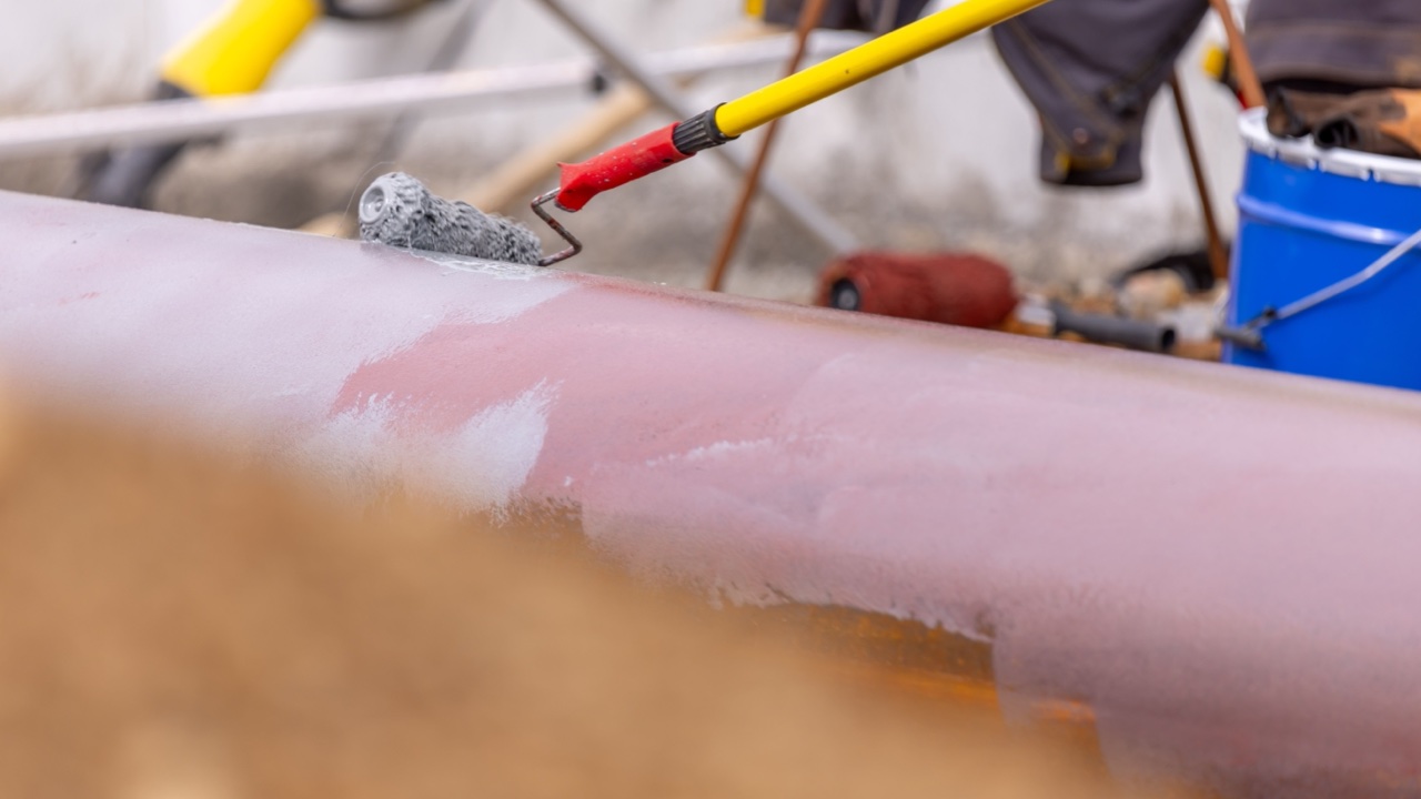
Cold-formed structural hollow sections arrive from the mill in a condition that’s fine for fabrication and erection, but not ideal for coating adhesion. The surface typically has mill scale — the dark, flaky iron oxide layer that forms during hot rolling — along with drawing compounds or light oils from the cold-forming process, and in fabricated assemblies, heat-affected zones around welds. Each of these interacts differently with primer systems, and treating all three the same way is one of the more reliable ways to end up with a coating that delamaminates ahead of its rated service life.
This matters particularly for AS/NZS 1163 C350 hollow sections used in exposed or corrosive environments — industrial structures near the coast, processing facilities, outdoor canopies, and anything where the coating is doing actual corrosion protection rather than just providing colour.
The Mill Scale Problem
Mill scale is not a surface contamination in the same sense as oil or dust — it’s an actual layer of iron oxides (primarily Fe₃O₄) that’s bonded to the steel surface. The problem isn’t that it’s dirty. The problem is that it’s cathodic relative to the underlying steel, and when moisture reaches the interface between mill scale and steel — either through pinholes in the coating or around damaged areas — the underlying steel corrodes preferentially. You end up with underfilm corrosion that spreads sideways under an apparently intact coating.
The solution is surface preparation that removes the mill scale before the primer goes on. The relevant standard in Australia and New Zealand is AS 1627.4 (abrasive blast cleaning of steel), which defines cleanliness grades from Class 1 (light abrasive blasting) through Class 3 (near-white metal). Most industrial primer systems for structural steelwork specify Class 2.5 or Class 3, which removes essentially all mill scale, rust, and contamination.
For C350 hollow sections, there’s no special accommodation for the grade — the preparation requirements come from the coating specification, not the steel grade. What does matter is that the hollow section geometry creates areas that are harder to blast effectively: internal corners on SHS and RHS, around welded gusset plates or end plates, and areas close to backing rings or internal diaphragms. These areas need attention during blast preparation to confirm adequate coverage.
Drawing Compound Residues
Cold-formed hollow sections are produced by drawing hot-rolled strip through forming rolls and then welding the longitudinal seam. This process uses lubricants — drawing compounds, forming oils, or light corrosion protection oils applied during or after production — that remain on the surface unless deliberately removed.
Oil contamination is particularly problematic for coating adhesion because it’s invisible and because even thin films interfere with the bond between primer and steel. Abrasive blasting alone doesn’t reliably remove oil — it can actually drive oil contamination deeper into the profile created by blasting. The correct sequence is degreasing first, then abrasive blasting.
AS 1627.1 covers solvent and alkaline cleaning methods. For fabricated assemblies that are going to be blast cleaned, degreasing before blasting is standard practice. For assemblies that will be power tool cleaned or hand tool cleaned instead of blasted, the degreasing step is even more important because the surface profile left by mechanical cleaning is typically shallower, giving less mechanical keying for the primer.
For hollow sections arriving from the mill with a visible oily film, the practical test is wiping a clean white rag across the surface. Any oil transfer indicates the steel needs degreasing before preparation. For assemblies from the fabricator, check specifically around weld areas where anti-spatter compounds may have been applied — these compounds are designed to resist weld spatter adhesion, but they have the same effect on primer adhesion and must be removed.
Weld Heat-Affected Zones
Welding creates a heat-affected zone in the adjacent parent material where the thermal cycle has altered the microstructure and surface oxide layer. At the weld bead itself and immediately adjacent, the oxide layer is a mix of weld spatter, weld flux (for flux-shielded processes), and thermally oxidised steel. This oxide has different adhesion characteristics than mill scale, and spatter creates high spots that can puncture coating films or create shadows where primer doesn’t reach.
Before coating, weld zones need specific preparation:
Weld spatter removal — Spatter is typically removed by chipping or grinding. The relevant requirement is that spatter be removed flush with the surrounding surface, not just knocked off to leave a rough stub. Remaining stubs create stress concentration points in the coating and sites where moisture accumulates.
Weld profile grinding where specified — High-build coatings and some protective coating systems specify that weld caps be ground to blend with the surrounding surface, reducing the sharp geometry at the weld toe that makes maintaining adequate film build difficult. Whether this is required depends on the coating specification, not on AS/NZS 1163 — the standard covers the hollow section material, not the coating applied in fabrication.
Flux residue removal — For processes that produce flux residue (submerged arc welding at the longitudinal seam, or manual metal arc used in fabrication), flux must be removed before blasting. Flux is water-soluble, and flux residues left under the coating absorb moisture and cause blistering. Water washing or abrasive blasting both remove flux, but confirm the blast clean follows any water washing after the steel has dried.
Surface Profile and the Primer System
Abrasive blasting doesn’t just clean the surface — it creates a profile, a microscopic roughness that mechanical anchors the primer to the steel. The profile depth required by the primer manufacturer needs to match what the blast operation produces. Most two-pack epoxy primers for structural steelwork require a profile of 40 to 75 microns Rz, achievable with steel shot or grit at appropriate blast pressure and nozzle condition.
For hollow sections, the profile requirement is the same as for any structural steel substrate. What’s worth confirming is that the blast medium and procedure used on the hollow section geometry (particularly inside box sections if these are to be coated internally) actually achieves the specified profile depth and cleanliness grade throughout, not just on easily accessible flat faces.
Timing Between Preparation and Priming
Blast-cleaned steel rerusts quickly in humid conditions. The standard window is typically priming within four hours of blast cleaning at relative humidity below 85 percent — a requirement that’s challenging in Queensland coastal conditions or during the wet season in Northern Australia.
Practical management of this on large fabrications involves sequencing the blast and prime operations so that blasted steel moves directly into the spray bay without sitting overnight. For large structural assemblies, partial blasting and priming in sections is usually more reliable than blasting an entire assembly and then losing the surface condition before priming is complete.
The documentation that records the preparation — blast grade achieved, profile measurement, time between blast and prime, ambient conditions — is part of the quality record for the project. For projects with an inspection and test plan, this data is typically required at hold points before the topcoat is applied. Getting the surface preparation right is part of making the structure perform as specified over its design life, not a step that can be skipped or abbreviated when the schedule is tight.
One Thing That Catches Fabricators Out
Sharp external corners on SHS and RHS create a challenge for coating application that’s different from the flat face of a plate. Coating films thin out at corners due to surface tension effects — a nominal 80 micron DFT on a flat face may be 30 to 40 microns at a sharp corner. Some coating specifications address this by requiring stripe coating of corners before the main coat, or by specifying a rounding of external corners (typically to a minimum 2 mm radius) during fabrication. If the project coating specification mentions corner treatment, this needs to be coordinated between the fabricator and the coating contractor before the hollow sections are cut and welded — grinding corners on an assembled structure is considerably more difficult than radiusing them at the saw before assembly.